| |
roboforum.ruТехнический форум по робототехнике. |
|
Мелкие кусочки на arduino
Сообщений: 41
• Страница 1 из 3 • 1, 2, 3
Мелкие кусочки на arduino
![]() hudbrog » 17 май 2009, 10:51
hudbrog » 17 май 2009, 10:51
Собственно, привезли мне таки arduino на растерзание.. начал его потихоньку мучать. Буду здесь выкладывать мини-отчетики по тому, что можно на нем сделать с фотками и исходниками. Просто чтоб если кто начал сим девайсом заниматься, была какая-нить инфа на русском языке.
-

hudbrog - Сообщения: 1585
- Зарегистрирован: 14 май 2008, 15:49
- Откуда: Москва
- ФИО: Алексей
Re: Мелкие кусочки на arduino
![]() EdGull » 17 май 2009, 10:56
EdGull » 17 май 2009, 10:56
Как будут материалы, заведем отдельный тематический раздел
-

EdGull - Сообщения: 10211
- Зарегистрирован: 28 дек 2004, 20:33
- Откуда: Тольятти
- Skype: Ed_Gull
- прог. языки: Bascom AVR Basic
- ФИО: Гуль Эдуард Викторович
Re: Мелкие кусочки на arduino
![]() hudbrog » 17 май 2009, 10:58
hudbrog » 17 май 2009, 10:58
Первое, что собрал - сканилка расстояний на сервере + УЗ дальнометре SRF-05. Времени затрачено на все - около полутора часов.
Вот так оно выглядит:

Вот такой результат на экране компьютера:

Там собственно по кругу показывается расстояние насканеное. Более-менее очевидно вроде как.
Вот код для Arduino:
А вот код для Processing чтобы получать данные с ардуины:
Вот так оно выглядит:
Вот такой результат на экране компьютера:
Там собственно по кругу показывается расстояние насканеное. Более-менее очевидно вроде как.
Вот код для Arduino:
- Код: Выделить всё • Развернуть
// Sweep
// by BARRAGAN <http://barraganstudio.com>

#include <Servo.h>

Servo myservo;  // create servo object to control a servo
                // a maximum of eight servo objects can be created

int pos = 0;    // variable to store the servo position
int pingPin = 2;


void setup()
{
  myservo.attach(9);  // attaches the servo on pin 9 to the servo object
  Serial.begin(57600);
}


void loop()
{
  long duration ,cm;
  pos+=1;
  if(pos>240){pos=0;myservo.write(pos);delay(600);}
//крутим серву на новое место
  myservo.write(pos);
//делаем запрос на srf-05
  pinMode(pingPin, OUTPUT);
  digitalWrite(pingPin, LOW);
  delayMicroseconds(2);
  digitalWrite(pingPin, HIGH);
  delayMicroseconds(10);
  digitalWrite(pingPin, LOW);
//получаем ответ
  pinMode(pingPin, INPUT);
  duration = pulseIn(pingPin, HIGH);
  cm = microsecondsToCentimeters(duration);
//фигачим в ком-порт положение сервы+расстояние до объекта через запятую
  Serial.print(pos, DEC);
  Serial.print(",");
  Serial.println(cm, DEC);
}

long microsecondsToCentimeters(long microseconds)
{
  // The speed of sound is 340 m/s or 29 microseconds per centimeter.
  // The ping travels out and back, so to find the distance of the
  // object we take half of the distance travelled.
  return microseconds / 29 / 2;
}
А вот код для Processing чтобы получать данные с ардуины:
- Код: Выделить всё • Развернуть
import processing.serial.*;

Serial port;

int[] values = new int[360];
String buff = "";
int NEWLINE = 10;
Boolean firstTime = true;


void setup()
{
  size(600, 600);
  String portName = Serial.list()[0];
  port = new Serial(this, portName, 57600);
  strokeWeight(2);
}


void draw()
{
  background(53);
  stroke(#00FF00);
  point(width/2, height/2);
  stroke(255);

  for (int i=0;i<359;i++){
    point(width/2+2*values[i]*sin(2*PI/360*i), height/2+2*values[i]*cos(2*PI/360*i));
  }
  while (port.available() > 0)
    serialEvent(port.read());
}

void serialEvent(int serial)
{
  if (serial != NEWLINE) {
    buff += char(serial);
  }
  else {
    if(firstTime){
      firstTime=false;
      buff="";
    }
    else{
      print(buff);
      try{
        buff = buff.substring(0, buff.length()-1);
        String []list = split(buff, ",");
        values[Integer.parseInt(list[0])] = Integer.parseInt(list[1]);
      }
      catch(Exception e)
      {
      }
      buff = "";
    }

  }
}
-
hudbrog - Сообщения: 1585
- Зарегистрирован: 14 май 2008, 15:49
- Откуда: Москва
- ФИО: Алексей
Re: Мелкие кусочки на arduino
![]() avr123.nm.ru » 17 май 2009, 12:37
avr123.nm.ru » 17 май 2009, 12:37
Я бы изменил крепление на серве чтоб УЗ датчик был ближе к оси сервы.
-

avr123.nm.ru - отсылающий читать курс
- Сообщения: 14195
- Зарегистрирован: 06 ноя 2005, 04:18
- Откуда: Москва
- Предупреждения: -8
Re: Мелкие кусочки на arduino
![]() galex1981 » 17 май 2009, 13:13
galex1981 » 17 май 2009, 13:13
А схема есть УЗ датчика, если есть можно выложить?
-

galex1981 - Сообщения: 4363
- Зарегистрирован: 04 дек 2008, 22:44
- Откуда: Камышин
- Skype: galk-aleksandr1
- прог. языки: Kotlin, Java, C, C++, Assm, BasCom, VB, php
- ФИО: Галкин Александр Владимирович
-

=DeaD= - Сообщения: 24218
- Зарегистрирован: 06 окт 2004, 18:01
- Откуда: Ебург
- прог. языки: C++ / PHP / 1C
- ФИО: Антон Ботов
-

blindman - Сообщения: 4130
- Зарегистрирован: 29 апр 2008, 21:15
- Откуда: Хабаровск
- прог. языки: C,C++,Assembler,PHP,Javascript,Ruby, SPIN,Java(?)
- ФИО: Андрей Юрьевич
Re: Мелкие кусочки на arduino
![]() =DeaD= » 17 май 2009, 14:19
=DeaD= » 17 май 2009, 14:19
Еще SRF08 есть -
Добавлено спустя 1 минуту 39 секунд:
SRF05 и правда не нашел пока открытую
Добавлено спустя 1 минуту 39 секунд:
SRF05 и правда не нашел пока открытую
-
=DeaD= - Сообщения: 24218
- Зарегистрирован: 06 окт 2004, 18:01
- Откуда: Ебург
- прог. языки: C++ / PHP / 1C
- ФИО: Антон Ботов
Re: Мелкие кусочки на arduino
![]() hudbrog » 17 май 2009, 23:10
hudbrog » 17 май 2009, 23:10
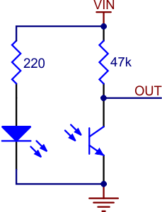
Датчик линии. Конкретно - QRB1114
Время на подключение - минут 15-20. Схема подключения нагло взята с сайта pololu, вот такая сложная схема:
Пока как мелкий строительный блок, потому просто выводим на экран показания датчика:

На графике поочередный переход с черного на белое и обратно.
Из интересного - видно, что даже на равномерном цвете показания датчика прыгают. Ну и что крайних возможных значений оно не достигает.
Скетч на ардуино даже не интересен:
На процессинге скетч не отличается от прошлого практически ничем, приводить не буду.
Добавлено спустя 2 минуты 26 секунд:
Все что тут делается - делается целенаправленно "на коленке" и не предназначено для дальнейшего использования напрямую, естественно. Я просто изучаю ардуино, поэтому к лежащим датчикам его подключаю поочередно, весь монтаж навесной, механические соединения - на двустороннем скотче.
Время на подключение - минут 15-20. Схема подключения нагло взята с сайта pololu, вот такая сложная схема:
Пока как мелкий строительный блок, потому просто выводим на экран показания датчика:
На графике поочередный переход с черного на белое и обратно.
Из интересного - видно, что даже на равномерном цвете показания датчика прыгают. Ну и что крайних возможных значений оно не достигает.
Скетч на ардуино даже не интересен:
- Код: Выделить всё • Развернуть
void setup()
{
  Serial.begin(57600);
}


void loop()
{
int val;
  val = analogRead(0);
  Serial.println(val, DEC);
  delay(100);
}
На процессинге скетч не отличается от прошлого практически ничем, приводить не буду.
Добавлено спустя 2 минуты 26 секунд:
avr123.nm.ru писал(а):Я бы изменил крепление на серве чтоб УЗ датчик был ближе к оси сервы.
Все что тут делается - делается целенаправленно "на коленке" и не предназначено для дальнейшего использования напрямую, естественно. Я просто изучаю ардуино, поэтому к лежащим датчикам его подключаю поочередно, весь монтаж навесной, механические соединения - на двустороннем скотче.
-
hudbrog - Сообщения: 1585
- Зарегистрирован: 14 май 2008, 15:49
- Откуда: Москва
- ФИО: Алексей
Re: Мелкие кусочки на arduino
![]() hudbrog » 18 май 2009, 10:31
hudbrog » 18 май 2009, 10:31
Собственно, косяки прошлого метода подключения:
Неравномерные данные, не полный возможный размах сигнала, куча шума. Ну и заодно запишем что работао только с одним датчиком линии.
Для исправления берем библиотеку Pololu QTR вот тут:
Пробуем использовать и выясняем что она нифига не работает =) Точнее работает при подключении сенсора через конденсатор и замере времени заряда, но не работает при обычном аналоговом подключении. Беда это поправимая, ниже приведу подправленный код. А вот так выглядят данные со сглаживанием, полученные после калибровки сенсора на конкретные условия:

Мягко скажем лучше. В реальности так красиво все равно выглядеть не будет, но и не будет тем страхом, что был раньше.
Вот исходник на ардуино:
А вот поправленный исходник библиотеки пололу:
Неравномерные данные, не полный возможный размах сигнала, куча шума. Ну и заодно запишем что работао только с одним датчиком линии.
Для исправления берем библиотеку Pololu QTR вот тут:
Пробуем использовать и выясняем что она нифига не работает =) Точнее работает при подключении сенсора через конденсатор и замере времени заряда, но не работает при обычном аналоговом подключении. Беда это поправимая, ниже приведу подправленный код. А вот так выглядят данные со сглаживанием, полученные после калибровки сенсора на конкретные условия:
Мягко скажем лучше. В реальности так красиво все равно выглядеть не будет, но и не будет тем страхом, что был раньше.
Вот исходник на ардуино:
- Код: Выделить всё • Развернуть
#include <PololuQTRSensors.h>

  PololuQTRSensorsAnalog qtra((unsigned char[]) {0,1}, 2);

void setup()
{
  Serial.begin(57600);
  int i;
   for (i = 0; i < 250; i++)  // make the calibration take about 5 seconds
   {
     qtra.calibrate();
     delay(20);
   }
}


void loop()
{
int val;
unsigned int sVals[2]={0,0};
  qtra.readCalibrated(sVals);
  val = sVals[0];
//  val = analogRead(0);
  Serial.println(val, DEC);
  delay(100);
}
А вот поправленный исходник библиотеки пололу:
- Код: Выделить всё • Развернуть
/*
  PololuQTRSensors.cpp - Library for using Pololu QTR reflectance
   sensors and reflectance sensor arrays: QTR-1A, QTR-8A, QTR-1RC, and
   QTR-8RC.  The object used will determine the type of the sensor (either
   QTR-xA or QTR-xRC).  Then simply specify in the constructor which
   Arduino I/O pins are connected to a QTR sensor, and the read() method
   will obtain reflectance measurements for those sensors.  Smaller sensor
   values correspond to higher reflectance (e.g. white) while larger
   sensor values correspond to lower reflectance (e.g. black or a void).

   * PololuQTRSensorsRC should be used for QTR-1RC and QTR-8RC sensors.
   * PololuQTRSensorsAnalog should be used for QTR-1A and QTR-8A sensors.
*/

/*
 * Written by Ben Schmidel et al., May 28, 2008.
 * Copyright (c) 2008 Pololu Corporation. For more information, see
 *
 *   http://www.pololu.com
 *   http://forum.pololu.com
 *   http://www.pololu.com/docs/0J18/9
 *
 * You may freely modify and share this code, as long as you keep this
 * notice intact (including the two links above).  Licensed under the
 * Creative Commons BY-SA 3.0 license:
 *
 *   http://creativecommons.org/licenses/by-sa/3.0/
 *
 * Disclaimer: To the extent permitted by law, Pololu provides this work
 * without any warranty.  It might be defective, in which case you agree
 * to be responsible for all resulting costs and damages.
 */

#ifndef F_CPU
#define F_CPU 20000000UL
#endif
#include <avr/io.h>
#include <stdlib.h>
#include "PololuQTRSensors.h"

#define QTR_RC      0
#define QTR_A      1

#ifdef LIB_POLOLU

#include "../OrangutanTime/OrangutanTime.h"      // provides access to delay routines
// two options for our sensors

// one pointer to the type in use
static PololuQTRSensors *qtr;

extern "C" void qtr_emitters_on()
{
   qtr->emittersOn();
}

extern "C" void qtr_emitters_off()
{
   qtr->emittersOff();
}

extern "C" char qtr_rc_init(unsigned char* pins, unsigned char numSensors,
             unsigned int timeout, unsigned char emitterPin)
{
   PololuQTRSensorsRC *qtr_rc = (PololuQTRSensorsRC *)malloc(sizeof(PololuQTRSensorsRC));
   if(!qtr_rc)
      return 0; // out of memory
   qtr_rc->init(pins, numSensors, timeout, emitterPin);
   qtr = qtr_rc;
   return 1;
}

extern "C" char qtr_analog_init(unsigned char* analogPins, unsigned char numSensors,
      unsigned char numSamplesPerSensor, unsigned char emitterPin)
{
   PololuQTRSensorsAnalog *qtr_analog = (PololuQTRSensorsAnalog *)malloc(sizeof(PololuQTRSensorsAnalog));
   if(!qtr_analog)
      return 0; // out of memory
   qtr_analog->init(analogPins, numSensors, numSamplesPerSensor, emitterPin);
   qtr = qtr_analog;
   return 1;
}

extern "C" void qtr_read(unsigned int *sensor_values, unsigned char readMode) {
   qtr->read(sensor_values,readMode);
}

extern "C" void qtr_calibrate(unsigned char readMode)
{
   qtr->calibrate(readMode);
}

extern "C" void qtr_read_calibrated(unsigned int *sensor_values, unsigned char readMode)
{
   qtr->readCalibrated(sensor_values, readMode);
}

extern "C" int qtr_read_line(unsigned int *sensor_values, unsigned char readMode)
{
   return qtr->readLine(sensor_values, readMode, false);
}

extern "C" int qtr_read_line_white(unsigned int *sensor_values, unsigned char readMode)
{
   return qtr->readLine(sensor_values, readMode, true);
}

#else
#include "wiring.h"      // provides access to delay() and delayMicroseconds()
#endif

// Base class data member initialization (called by derived class init())
void PololuQTRSensors::init(unsigned char numSensors,
  unsigned char emitterPin, unsigned char type)
{
   calibratedMinimumOn=0;
   calibratedMaximumOn=0;
   calibratedMinimumOff=0;
   calibratedMaximumOff=0;

   if (numSensors > 8)
      _numSensors = 8;
   else
      _numSensors = numSensors;

   _type = type;

   if (emitterPin < 8)            // port D
   {
      _emitterBitmask = 1 << emitterPin;
      _emitterPORT = &PORTD;
      _emitterDDR = &DDRD;
   }
   else if (emitterPin < 14)      // port B
   {
      _emitterBitmask = 1 << (emitterPin - 8);
      _emitterPORT = &PORTB;
      _emitterDDR = &DDRB;
   }
   else if (emitterPin < 20)      // port C
   {
      _emitterBitmask = 1 << (emitterPin - 14);
      _emitterPORT = &PORTC;
      _emitterDDR = &DDRC;
   }
   else
   {
      _emitterDDR = 0;
      _emitterPORT = 0;
   }
}


// Reads the sensor values into an array. There *MUST* be space
// for as many values as there were sensors specified in the constructor.
// Example usage:
// unsigned int sensor_values[8];
// sensors.read(sensor_values);
// The values returned are a measure of the reflectance in abstract units,
// with higher values corresponding to lower reflectance (e.g. a black
// surface or a void).
void PololuQTRSensors::read(unsigned int *sensor_values, unsigned char readMode)
{
   unsigned int off_values[8];
   unsigned char i;

   if(readMode == QTR_EMITTERS_ON || readMode == QTR_EMITTERS_ON_AND_OFF)
      emittersOn();

   if (_type == QTR_RC)
   {
      ((PololuQTRSensorsRC*)this)->readPrivate(sensor_values);
      emittersOff();
      if(readMode == QTR_EMITTERS_ON_AND_OFF)
         ((PololuQTRSensorsRC*)this)->readPrivate(off_values);
   }
   else
   {
      ((PololuQTRSensorsAnalog*)this)->readPrivate(sensor_values);
      emittersOff();
      if(readMode == QTR_EMITTERS_ON_AND_OFF)
         ((PololuQTRSensorsRC*)this)->readPrivate(off_values);
   }

   if(readMode == QTR_EMITTERS_ON_AND_OFF)
   {
      for(i=0;i<_numSensors;i++)
      {
         sensor_values[i] += _maxValue - off_values[i];
      }
   }
}


// Turn the IR LEDs off and on.  This is mainly for use by the
// read method, and calling these functions before or
// after the reading the sensors will have no effect on the
// readings, but you may wish to use these for testing purposes.
void PololuQTRSensors::emittersOff()
{
   if (_emitterDDR == 0)
      return;
   *_emitterDDR |= _emitterBitmask;
   *_emitterPORT &= ~_emitterBitmask;
}

void PololuQTRSensors::emittersOn()
{
  if (_emitterDDR == 0)
      return;
   *_emitterDDR |= _emitterBitmask;
   *_emitterPORT |= _emitterBitmask;
}


// Reads the sensors 10 times and uses the results for
// calibration.  The sensor values are not returned; instead, the
// maximum and minimum values found over time are stored internally
// and used for the readCalibrated() method.
void PololuQTRSensors::calibrate(unsigned char readMode)
{
   if(readMode == QTR_EMITTERS_ON_AND_OFF || readMode == QTR_EMITTERS_ON)
   {
      calibrateOnOrOff(&calibratedMinimumOn,
                   &calibratedMaximumOn,
                   QTR_EMITTERS_ON);
   }


   if(readMode == QTR_EMITTERS_ON_AND_OFF || readMode == QTR_EMITTERS_OFF)
   {
      calibrateOnOrOff(&calibratedMinimumOff,
                   &calibratedMaximumOff,
                   QTR_EMITTERS_OFF);
   }
}

void PololuQTRSensors::calibrateOnOrOff(unsigned int **calibratedMinimum,
                              unsigned int **calibratedMaximum,
                              unsigned char readMode)
{
   int i;
   unsigned int sensor_values[8];
   unsigned int max_sensor_values[8];
   unsigned int min_sensor_values[8];

   // Allocate the arrays if necessary.
   if(*calibratedMaximum == 0)
   {
      *calibratedMaximum = (unsigned int*)malloc(sizeof(unsigned int)*_numSensors);

      // If the malloc failed, don't continue.
      if(*calibratedMaximum == 0)
         return;

      // Initialize the max and min calibrated values to values that
      // will cause the first reading to update them.

      for(i=0;i<_numSensors;i++)
         (*calibratedMaximum)[i] = 0;
   }
   if(*calibratedMinimum == 0)
   {
      *calibratedMinimum = (unsigned int*)malloc(sizeof(unsigned int)*_numSensors);

      // If the malloc failed, don't continue.
      if(*calibratedMinimum == 0)
         return;

      for(i=0;i<_numSensors;i++)
         (*calibratedMinimum)[i] = _maxValue;
   }

   int j;
   for(j=0;j<10;j++)
   {
      read(sensor_values,readMode);
      for(i=0;i<_numSensors;i++)
      {
         // set the max we found THIS time
         if(j == 0 || max_sensor_values[i] < sensor_values[i])
            max_sensor_values[i] = sensor_values[i];

         // set the min we found THIS time
         if(j == 0 || min_sensor_values[i] > sensor_values[i])
            min_sensor_values[i] = sensor_values[i];
      }
   }

   // record the min and max calibration values
   for(i=0;i<_numSensors;i++)
   {
      if(min_sensor_values[i] > (*calibratedMaximum)[i])
         (*calibratedMaximum)[i] = min_sensor_values[i];
      if(max_sensor_values[i] < (*calibratedMinimum)[i])
         (*calibratedMinimum)[i] = max_sensor_values[i];
   }
}


// Returns values calibrated to a value between 0 and 1000, where
// 0 corresponds to the minimum value read by calibrate() and 1000
// corresponds to the maximum value.  Calibration values are
// stored separately for each sensor, so that differences in the
// sensors are accounted for automatically.
void PololuQTRSensors::readCalibrated(unsigned int *sensor_values, unsigned char readMode)
{
   int i;

   // if not calibrated, do nothing
   if(readMode == QTR_EMITTERS_ON_AND_OFF || readMode == QTR_EMITTERS_OFF)
      if(!calibratedMinimumOff || !calibratedMaximumOff)
         return;
   if(readMode == QTR_EMITTERS_ON_AND_OFF || readMode == QTR_EMITTERS_ON)
      if(!calibratedMinimumOn || !calibratedMaximumOn)
         return;

   // read the needed values
   read(sensor_values,readMode);

   for(i=0;i<_numSensors;i++)
   {
      unsigned int calmin,calmax;
      unsigned int denominator;

      // find the correct calibration
      if(readMode == QTR_EMITTERS_ON)
      {
         calmax = calibratedMaximumOn[i];
          calmin = calibratedMinimumOn[i];
      }
      else if(readMode == QTR_EMITTERS_OFF)
      {
         calmax = calibratedMaximumOff[i];
          calmin = calibratedMinimumOff[i];
      }
      else // QTR_EMITTERS_ON_AND_OFF
      {

         if(calibratedMinimumOff[i] < calibratedMinimumOn[i]) // no meaningful signal
            calmin = _maxValue;
         else
            calmin = calibratedMinimumOn[i] + _maxValue - calibratedMinimumOff[i]; // this won't go past _maxValue

         if(calibratedMaximumOff[i] < calibratedMaximumOn[i]) // no meaningful signal
            calmax = _maxValue;
         else
            calmax = calibratedMaximumOn[i] + _maxValue - calibratedMaximumOff[i]; // this won't go past _maxValue
      }

      denominator = calmax - calmin;

      signed int x = 0;
      if(denominator != 0)
         x = (((signed long)sensor_values[i]) - calmin)
            * 1000 / denominator;
      if(x < 0)
         x = 0;
      else if(x > 1000)
         x = 1000;
      sensor_values[i] = x;
   }

}


// Operates the same as read calibrated, but also returns an
// estimated position of the robot with respect to a line. The
// estimate is made using a weighted average of the sensor indices
// multiplied by 1000, so that a return value of 0 indicates that
// the line is directly below sensor 0, a return value of 1000
// indicates that the line is directly below sensor 1, 2000
// indicates that it's below sensor 2000, etc.  Intermediate
// values indicate that the line is between two sensors.  The
// formula is:
//
//    0*value0 + 1000*value1 + 2000*value2 + ...
//   --------------------------------------------
//         value0  +  value1  +  value2 + ...
//
// By default, this function assumes a dark line (high values)
// surrounded by white (low values).  If your line is light on
// black, set the optional second argument white_line to true.  In
// this case, each sensor value will be replaced by (1000-value)
// before the averaging.
int PololuQTRSensors::readLine(unsigned int *sensor_values,
   unsigned char readMode, unsigned char white_line)
{
   unsigned char i, on_line = 0;
   unsigned long avg; // this is for the weighted total, which is long
                      // before division
   unsigned int sum; // this is for the denominator which is <= 64000
   static int last_value=0; // assume initially that the line is left.

   readCalibrated(sensor_values, readMode);

   avg = 0;
   sum = 0;

   for(i=0;i<_numSensors;i++) {
      int value = sensor_values[i];
      if(white_line)
         value = 1000-value;

      // keep track of whether we see the line at all
      if(value > 200) {
         on_line = 1;
      }

      // only average in values that are above a noise threshold
      if(value > 50) {
         avg += (long)(value) * (i * 1000);
         sum += value;
      }
   }

   if(!on_line)
   {
      // If it last read to the left of center, return 0.
      if(last_value < (_numSensors-1)*1000/2)
         return 0;

      // If it last read to the right of center, return the max.
      else
         return (_numSensors-1)*1000;

   }

   last_value = avg/sum;

   return last_value;
}


// Derived RC class constructor
PololuQTRSensorsRC::PololuQTRSensorsRC(unsigned char* pins,
  unsigned char numSensors, unsigned int timeout, unsigned char emitterPin)
{
   init(pins, numSensors, timeout, emitterPin);
}


// the array 'pins' contains the Arduino pin assignment for each
// sensor.  For example, if pins is {3, 6, 15}, sensor 1 is on
// Arduino digital pin 3, sensor 2 is on Arduino digital pin 6,
// and sensor 3 is on Arduino analog input 1 (digital pin 15).
// Note that Arduino digital pins 0 - 7 correpsond to port D
// pins PD0 - PD7, respectively.  Arduino digital pins 8 - 13
// correspond to port B pins PB0 - PB5.  Arduino analog inputs
// 0 - 5 are referred to as digital pins 14 - 19 (these are the
// enumerations you should use for this library) and correspond
// to port C pins PC0 - PC5.

// 'numSensors' specifies the length of the 'pins' array (i.e. the
// number of QTR-RC sensors you are using).  numSensors must be
// no greater than 8.

// 'timeout' specifies the length of time in timer2 counts beyond
// which you consider the sensor reading completely black.  That is to say,
// if the pulse length for a pin exceeds 'timeout', pulse timing will stop
// and the reading for that pin will be considered full black.
// It is recommended that you set timeout to be between 1000 and
// 3000 us, depending on things like the height of your sensors and
// ambient lighting.  Using timeout allows you to shorten the
// duration of a sensor-reading cycle while still maintaining
// useful analog measurements of reflectance.  On a 16 MHz microcontroller,
// you can convert timer2 counts to microseconds by dividing by 2
// (i.e. 2000 us = 4000 timer2 counts = 'timeout' of 4000).  On a 20 MHz
// microcontroller, you can convert timer2 counts to microseconds by
// dividing by 2.5 or multiplying by 0.4
// (i.e. 2000 us = 5000 timer2 counts = 'timeout' of 5000).

// 'emitterPin' is the Arduino pin that controls the IR LEDs on the 8RC
// modules.  If you are using a 1RC (i.e. if there is no emitter pin),
// use an invalid Arduino pin value (20 or greater).
void PololuQTRSensorsRC::init(unsigned char* pins,
   unsigned char numSensors, unsigned int timeout, unsigned char emitterPin)
{
   PololuQTRSensors::init(numSensors, emitterPin, QTR_RC);

   unsigned char i;
   _portBMask = 0;
   _portCMask = 0;
   _portDMask = 0;

   _maxValue = timeout;
   for (i = 0; i < _numSensors; i++)
   {
      if (pins[i] < 8)         // port D
      {
         _bitmask[i] = 1 << pins[i];
         _portDMask |= _bitmask[i];
         _register[i] = &PIND;
      }
      else if (pins[i] < 14)      // port B
      {
         _bitmask[i] = 1 << (pins[i] - 8);
         _portBMask |= _bitmask[i];
         _register[i] = &PINB;
      }
      else if (pins[i] < 20)      // port C
      {
         _bitmask[i] = 1 << (pins[i] - 14);
         _portCMask |= _bitmask[i];
         _register[i] = &PINC;
      }
   }
}


// Reads the sensor values into an array. There *MUST* be space
// for as many values as there were sensors specified in the constructor.
// Example usage:
// unsigned int sensor_values[8];
// sensors.read(sensor_values);
// ...
// The values returned are in microseconds and range from 0 to
// timeout_us (as specified in the constructor).
void PololuQTRSensorsRC::readPrivate(unsigned int *sensor_values)
{
   unsigned char i;
   unsigned char start_time;
   unsigned char delta_time;
   unsigned int time = 0;

   unsigned char last_b = _portBMask;
   unsigned char last_c = _portCMask;
   unsigned char last_d = _portDMask;

   // reset the values
   for(i = 0; i < _numSensors; i++)
      sensor_values[i] = 0;

   // set all sensor pins to outputs
   DDRB |= _portBMask;
   DDRC |= _portCMask;
   DDRD |= _portDMask;

   // drive high for 10 us
   PORTB |= _portBMask;
   PORTC |= _portCMask;
   PORTD |= _portDMask;

   delayMicroseconds(10);

   // set all ports to inputs
   DDRB &= ~_portBMask;
   DDRC &= ~_portCMask;
   DDRD &= ~_portDMask;

   // turn off pull ups
   PORTB &= ~_portBMask;
   PORTC &= ~_portCMask;
   PORTD &= ~_portDMask;

   unsigned char prevTCCR2A = TCCR2A;
   unsigned char prevTCCR2B = TCCR2B;
   TCCR2A |= 0x03;
   TCCR2B = 0x02;      // run timer2 in normal mode at 2.5 MHz
                  // this is compatible with OrangutanMotors


   start_time = TCNT2;
   while (time < _maxValue)
   {
      // Keep track of the total time.
      // This explicitly casts the difference to unsigned char, so
      // we don't add negative values.
      delta_time = TCNT2 - start_time;
      time += delta_time;
      start_time += delta_time;

      // continue immediately if there is no change
      if (PINB == last_b && PINC == last_c && PIND == last_d)
         continue;

      // save the last observed values
      last_b = PINB;
      last_c = PINC;
      last_d = PIND;

      // figure out which pins changed
      for (i = 0; i < _numSensors; i++)
      {
         if (sensor_values[i] == 0 && !(*_register[i] & _bitmask[i]))
            sensor_values[i] = time;
      }
   }

   TCCR2A = prevTCCR2A;
   TCCR2B = prevTCCR2B;
   for(i = 0; i < _numSensors; i++)
      if (!sensor_values[i])
         sensor_values[i] = _maxValue;
}


// Derived Analog class constructor
PololuQTRSensorsAnalog::PololuQTRSensorsAnalog(unsigned char* analogPins,
  unsigned char numSensors, unsigned char numSamplesPerSensor,
  unsigned char emitterPin)
{
   init(analogPins, numSensors, numSamplesPerSensor, emitterPin);
}


// the array 'pins' contains the Arduino analog pin assignment for each
// sensor.  For example, if pins is {0, 1, 7}, sensor 1 is on
// Arduino analog input 0, sensor 2 is on Arduino analog input 1,
// and sensor 3 is on Arduino analog input 7.  The ATmega168 has 8
// total analog input channels (0 - 7) that correspond to port C
// pins PC0 - PC7.

// 'numSensors' specifies the length of the 'analogPins' array (i.e. the
// number of QTR-A sensors you are using).  numSensors must be
// no greater than 8.

// 'numSamplesPerSensor' indicates the number of 10-bit analog samples
// to average per channel (i.e. per sensor) for each reading.  The total
// number of analog-to-digital conversions performed will be equal to
// numSensors*numSamplesPerSensor.  Note that the amount of time it takes
// to perform a single analog-to-digital conversion is approximately:
// 128 * 13 / F_CPU = 1664 / F_CPU
// If F_CPU is 16 MHz, as on most Arduinos, this becomes:
// 1664 / 16 MHz = 104 us
// So if numSamplesPerSensor is 4 and numSensors is, say, 6, it will take
// 4 * 6 * 104 us = 2.5 ms to perform a full readLine() if F_CPU is 16 MHz.
// Increasing this parameter increases noise suppression at the cost of
// sample rate.  Recommended value: 4.

// emitterPin is the Arduino digital pin that controls whether the IR LEDs
// are on or off.  This pin is optional and only exists on the 8A and 8RC
// QTR sensor arrays.  If a valid pin is specified, the emitters will only
// be turned on during a reading.  If an invalid pin is specified
// (e.g. 255), the IR emitters will always be on.
void PololuQTRSensorsAnalog::init(unsigned char* analogPins,
   unsigned char numSensors, unsigned char numSamplesPerSensor,
   unsigned char emitterPin)
{
   unsigned char i;

   PololuQTRSensors::init(numSensors, emitterPin, QTR_A);

   _numSamplesPerSensor = numSamplesPerSensor;
   _portCMask = 0;
   for (i = 0; i < _numSensors; i++)
   {
      _analogPins[i] = analogPins[i];
      if (analogPins[i] <= 5)   // no need to mask for dedicated analog inputs
         _portCMask |= (1 << analogPins[i]);
   }

   _maxValue = 1021; // this is the maximum returned by the A/D conversion
}


// Reads the sensor values into an array. There *MUST* be space
// for as many values as there were sensors specified in the constructor.
// Example usage:
// unsigned int sensor_values[8];
// sensors.read(sensor_values);
// The values returned are a measure of the reflectance in terms of a
// 10-bit ADC average with higher values corresponding to lower
// reflectance (e.g. a black surface or a void).
void PololuQTRSensorsAnalog::readPrivate(unsigned int *sensor_values)
{
   unsigned char i, j;
   for (j = 0; j < _numSamplesPerSensor; j++)
   {
      for (i = 0; i < _numSensors; i++)
      {
         sensor_values[i] += analogRead(_analogPins[i]);
      }
   }

   for (i = 0; i < _numSensors; i++)
      sensor_values[i] = (sensor_values[i] + (_numSamplesPerSensor >> 1)) /
         _numSamplesPerSensor;


}

// the destructor frees up allocated memory
PololuQTRSensors::~PololuQTRSensors()
{
   if(calibratedMaximumOn)
      free(calibratedMaximumOn);
   if(calibratedMaximumOff)
      free(calibratedMaximumOff);
   if(calibratedMinimumOn)
      free(calibratedMinimumOn);
   if(calibratedMinimumOff)
      free(calibratedMinimumOff);
}


// Local Variables: **
// mode: C++ **
// c-basic-offset: 4 **
// tab-width: 4 **
// indent-tabs-mode: t **
// end: **
-
hudbrog - Сообщения: 1585
- Зарегистрирован: 14 май 2008, 15:49
- Откуда: Москва
- ФИО: Алексей
-

Виталий - Сообщения: 2114
- Зарегистрирован: 08 окт 2004, 16:43
- Откуда: St. Petersburg
- Skype: quark-bot
- ФИО: Клебан Виталий
Re: Мелкие кусочки на arduino
![]() EdGull » 18 май 2009, 12:27
EdGull » 18 май 2009, 12:27
кстати, а где цены на всё то что здесь описывается?
-
EdGull - Сообщения: 10211
- Зарегистрирован: 28 дек 2004, 20:33
- Откуда: Тольятти
- Skype: Ed_Gull
- прог. языки: Bascom AVR Basic
- ФИО: Гуль Эдуард Викторович
Re: Мелкие кусочки на arduino
![]() hudbrog » 18 май 2009, 12:38
hudbrog » 18 май 2009, 12:38
Виталий: угу, ардуино зачет
EdGull, я даже боюсь поинтересоваться, на что цены? здесь описываются методы подключения сенсоров к ардуино и приводятся исходники для последнего. Первое сообщение темы читали?
EdGull, я даже боюсь поинтересоваться, на что цены? здесь описываются методы подключения сенсоров к ардуино и приводятся исходники для последнего. Первое сообщение темы читали?
-
hudbrog - Сообщения: 1585
- Зарегистрирован: 14 май 2008, 15:49
- Откуда: Москва
- ФИО: Алексей
Re: Мелкие кусочки на arduino
![]() EdGull » 18 май 2009, 12:40
EdGull » 18 май 2009, 12:40
вот именно из первого постаи и исходил.
без цен на комплектующие и сроков доставки картина будет не полная для начинающих.
без цен на комплектующие и сроков доставки картина будет не полная для начинающих.
-
EdGull - Сообщения: 10211
- Зарегистрирован: 28 дек 2004, 20:33
- Откуда: Тольятти
- Skype: Ed_Gull
- прог. языки: Bascom AVR Basic
- ФИО: Гуль Эдуард Викторович
Re: Мелкие кусочки на arduino
![]() =DeaD= » 18 май 2009, 12:49
=DeaD= » 18 май 2009, 12:49
2EdGull: Так вроде никто здесь не продвигает ардуино как платформу для начинающих  два человека обменялись мнениями что это круто с их субъективной точки зрения, никому не навязывали ничего... вроде... тем более не ясно с чего люди вдруг кинутся описывать сроки и цены доставки, растаможки и т.п.
два человека обменялись мнениями что это круто с их субъективной точки зрения, никому не навязывали ничего... вроде... тем более не ясно с чего люди вдруг кинутся описывать сроки и цены доставки, растаможки и т.п.-
=DeaD= - Сообщения: 24218
- Зарегистрирован: 06 окт 2004, 18:01
- Откуда: Ебург
- прог. языки: C++ / PHP / 1C
- ФИО: Антон Ботов
Сообщений: 41
• Страница 1 из 3 • 1, 2, 3
Вернуться в Arduino и другие Xduino
Кто сейчас на конференции
Сейчас этот форум просматривают: нет зарегистрированных пользователей и гости: 0