Есть ATMega32. В CodeVisionAVR (1.25.9 Pro) USART сконфигурирован. В хелпе сказано что с ним надо работать стандартными средствами putchar, getchar, и т.д. Посылаю байт в него, ничего не происходит. Что я делаю не так. Подскажите, пожалуйста, как работать
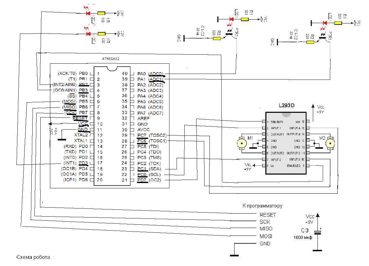
P.S. самое проблемное! помогите его подключить, пожалуйста!
http://myrobot.ru/stepbystep/r_firstbot2.php - ????????


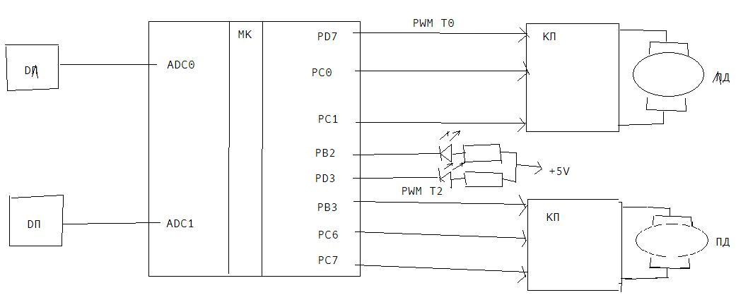
ЛД: PC=0x01 - назад
___PC=0x02 - вперед
ПД: PC=0x40 - назад
___PC=0x80 - вперед
- Код: Выделить всё
/*****************************************************
This program was produced by the
CodeWizardAVR V1.25.9 Standard
Automatic Program Generator
© Copyright 1998-2008 Pavel Haiduc, HP InfoTech s.r.l.
http://www.hpinfotech.com

Project :
Version :
Date    : 17.04.2012
Author  : F4CG
Company : F4CG
Comments:


Chip type           : ATmega32
Program type        : Application
Clock frequency     : 16,000000 MHz
Memory model        : Small
External SRAM size  : 0
Data Stack size     : 512
*****************************************************/

#include <mega32.h>
#include <delay.h>
#include <stdio.h>
#define ADC_VREF_TYPE 0x60
#define kont 200
#define sp 0x41
#define sp1 0x82

// External Interrupt 0 service routine
interrupt [EXT_INT0] void ext_int0_isr(void)
{
// Place your code here
}
// External Interrupt 1 service routine
interrupt [EXT_INT1] void ext_int1_isr(void)
{
// Place your code here
}
// External Interrupt 2 service routine
interrupt [EXT_INT2] void ext_int2_isr(void)
{
// Place your code here
}
 // Declare your global variables here

// Read the 8 most significant bits
// of the AD conversion result
unsigned char read_adc(unsigned char adc_input)
{
ADMUX=adc_input | (ADC_VREF_TYPE & 0xff);
// Delay needed for the stabilization of the ADC input voltage
delay_us(10);
// Start the AD conversion
ADCSRA|=0x40;
// Wait for the AD conversion to complete
while ((ADCSRA & 0x10)==0);
ADCSRA|=0x10;
return ADCH;
}

// Declare your global variables here
unsigned int a1, a2;
//double d;

void main(void)
{

// Input/Output Ports initialization
// Port A initialization
// Func7=In Func6=In Func5=In Func4=In Func3=In Func2=In Func1=In Func0=In
// State7=T State6=T State5=T State4=T State3=T State2=T State1=T State0=T
PORTA=0x00;
DDRA=0x00;

// Port B initialization
// Func7=In Func6=In Func5=In Func4=In Func3=Out Func2=In Func1=In Func0=In
// State7=T State6=T State5=T State4=T State3=0 State2=T State1=T State0=T
PORTB=0x00;
DDRB=0x0C;

// Port C initialization
// Func7=Out Func6=Out Func5=In Func4=In Func3=In Func2=In Func1=Out Func0=Out
// State7=0 State6=0 State5=T State4=T State3=T State2=T State1=0 State0=0
PORTC=0x00;
DDRC=0xC3;

// Port D initialization
// Func7=Out Func6=In Func5=In Func4=In Func3=In Func2=In Func1=In Func0=In
// State7=0 State6=T State5=T State4=T State3=T State2=T State1=T State0=T
PORTD=0x00;
DDRD=0x88;


// Timer/Counter 0 initialization
// Clock source: System Clock
// Clock value: 250,000 kHz
// Mode: Fast PWM top=FFh
// OC0 output: Non-Inverted PWM
TCCR0=0x6B;
TCNT0=0x00;
OCR0=0x5F;

// Timer/Counter 1 initialization
// Clock source: System Clock
// Clock value: Timer 1 Stopped
// Mode: Normal top=FFFFh
// OC1A output: Discon.
// OC1B output: Discon.
// Noise Canceler: Off
// Input Capture on Falling Edge
// Timer 1 Overflow Interrupt: Off
// Input Capture Interrupt: Off
// Compare A Match Interrupt: Off
// Compare B Match Interrupt: Off
TCCR1A=0x00;
TCCR1B=0x00;
TCNT1H=0x00;
TCNT1L=0x00;
ICR1H=0x00;
ICR1L=0x00;
OCR1AH=0x00;
OCR1AL=0x00;
OCR1BH=0x00;
OCR1BL=0x00;


// Timer/Counter 2 initialization
// Clock source: System Clock
// Clock value: 250,000 kHz
// Mode: Fast PWM top=FFh
// OC2 output: Non-Inverted PWM
ASSR=0x00;
TCCR2=0x6C;
TCNT2=0x00;
OCR2=0x5F;

// External Interrupt(s) initialization
// INT0: Off
// INT1: Off
// INT2: Off
MCUCR=0x00;
MCUCSR=0x00;

// Timer(s)/Counter(s) Interrupt(s) initialization
TIMSK=0x00;

/// USART initialization
// Communication Parameters: 8 Data, 1 Stop, No Parity
// USART Receiver: On
// USART Transmitter: On
// USART Mode: Asynchronous
// USART Baud Rate: 38400
UCSRA=0x00;
UCSRB=0x18;
UCSRC=0x86;
UBRRH=0x00;
UBRRL=0x19;

// Analog Comparator initialization
// Analog Comparator: Off
// Analog Comparator Input Capture by Timer/Counter 1: Off
ACSR=0x80;
SFIOR=0x00;

// ADC initialization
// ADC Clock frequency: 125,000 kHz
// ADC Voltage Reference: AVCC pin
// ADC Auto Trigger Source: Free Running
// Only the 8 most significant bits of
// the AD conversion result are used
ADMUX=ADC_VREF_TYPE & 0xff;
ADCSRA=0xA7;
SFIOR&=0x1F;

#asm("sei")

while (1)
      {
      // Place your code here

     a1 = read_adc(0);
     putchar('1');
     putchar(':');
     printf("%d\r", a1);

     a2 = read_adc(1);
     putchar('2');
     putchar(':');
     printf("%d\r", a2);

     putchar('\r');
     putchar('\r');


//     PORTB.2=1;
  //   PORTD.3=1;

     PORTB.3=1;//ПРАВОЕ
     PORTD.7=1;//ЛЕВОЕ

     OCR0=sp;
     OCR2=sp;

      if (a1<kont && a2<kont )
//{
      delay_ms(10);
          if (a1<kont && a2<kont )
          {
          PORTC.0=0;
          PORTC.6=0;
          PORTC.1=1;
          PORTC.7=1;
          }
          else
          {
          if (a1<kont)  //na pravo povorot
                {
                OCR0=0x01;
                OCR2=0x01;
                PORTC.7=0;
                PORTC.6=1;
                }
                else
                        {
                        PORTC.6=0;
                        PORTC.7=1;
                        OCR0=sp1;
                        OCR2=sp1;
                        }
                if (a2<kont)        //na levo povorot
                {

                PORTC.1=0;
                PORTC.0=1;
                OCR0=0x40;
                OCR2=0x40;
                }
                else
                        {
                        PORTC.0=0;
                        PORTC.1=1;
                        OCR0=sp1;
                        OCR2=sp1;
                        }
           }
    } ;
}


